communications
System Level Block Diagram

Channel
No channel equalization will occur in the system. The primary reason for this is that the system is essentially a line-of-sight channel, with an assumed flat frequency response and no multipath effects. The channel will have additive, white Gaussian noise (AWGN), due to thermal noise in the link. An analysis of the noise level is shown in the link budget
Source Coding
To handle source coding on the video stream, a H.264 (MPEG-4 Part 10) video encoder is used. The video encoder is implemented on a FPGA, with the core purchases from 4i2i Communications Ltd. The video will be encoded at 15 fps, with a resolution of 1280x720 (720p) to satisfy the high-definition requirements.
For source coding of still images, the processor compresses the images using a lossless method. The lossless method chosen is the TIFF file format, using LZW compression. Using these settings, a typical still image at 1280x720 resolution will occupy 2-3 megabytes of space on average.
Channel Coding
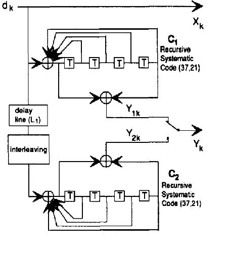
To handle forward error-correction coding, a parallel concatenated turbo code is used. A turbo coder is very simple to implement on the satellite system. A turbo decoder is not necessary in any capacity on the moon, simplifying the complexity of hardware necessary for the mission. The turbo encoding is done by the lunar lander’s microprocessor. For reasons explained in the decoding section, the first encoder should end in a known state (state 0). This trellis termination is accomplished for the first stream by appending additional bits. A basic block diagram of a turbo encoder is shown below (taken from the paper by Berrou, Glavieux, and Thitimajshima):
Decoding of the turbo code can be done using a variety of different methods. One choice would be use a modification of the BCJR algorithm, which is a soft-input, soft-output algorithm. A basic block diagram of the decoding process is shown below, taken from [3]

The first half-decoder takes the intrinsic information (noisy message bits and noisy parity bits) and computes a forward recursion and a backward recursion for each bit. Using these recursions, the probability that the encoder was in a given state s can be calculated. Since the structure of the encoder is known, only certain state transitions are possible. It is known that the encoder starts and ends in state 0, so the recursions can be initialize with certainty.
The extrinsic information from the first decoder is then fed into a second turbo half-decoder after being interleaved. The process is virtually identical to the first half-decoder, except that the second decoder has a non-terminated trellis and uses the second set of noisy parity check bits. This half-decoder then computes extrinsic information which can be fed back into the first decoder. The process can be repeated for a number of iterations.
We wrote our own turbo coder and the MATLAB source code can be found here. Maximum coding gain that can be achieved using the best turbo encoder is about 10 dB. The performance of our own MATLAB simulated Turbo coder is shown below.

When implementing a turbo code, an important consideration is when to terminate the turbo decoding process. One possible method is by using a fixed number of iterations on decoding, but this may run an unnecessarily high number of iterations or too few iterations. One easy solution to this problem is by framing the data in such a way that 32-bit cyclic redundancy check (CRC) of the data is also included. The decoding process stops when the decoded data matches the CRC in the frame. This will give performance very close to the curve with the maximum number of iterations, as shown above.